Capstone 1 Blog Post 3: Progress Update
- Raphael Luu
- Nov 11, 2023
- 4 min read

Since October 28 until now, the first milestone of Initial Design Developed has been completed with some progress made into the second milestone of Final Design Completed. This is due to a major delay caused by a significant change in the project scope. The finalized project scope is to design and fabricate a 1:10 scale model mechanical spray system for a AT502B crop duster that repositions the spray boom 0.15 ft lower and 0.12 ft forward from its original position, without inducing greater drag than the original spray system design.
Prior to the change in scope, the CAD of the existing spray system and crop duster had been completed, initial design for the mechanism to move the spray system was explored, and research into learning CFD with Ansys Fluent was started. A total of 24 hanger designs with varying reductions in surface area and geometric profiles have been developed to reduce the drag force of the lowered mechanical system and have been analyzed by CFD. Table 1 shows the corresponding drag and surface area for each of the models. Model 5.2 has proven to be the design that induces the least drag.
The largest obstacle that the team is still facing is designing a hanger that can both reach the desired lowered position and maintain equivalent or less drag than the original hanger. Three different variations of CFD simulations have been run, one with the hanger and the wing’s airfoil cross section considered as one body, the second with only the hanger as the body without the airfoil cross section, and the final with the airfoil and the hanger as separate bodies. Upon consultation with Professor Love, the third option would yield the most accurate results. Using the second option, several hanger designs have been able to induce less drag than the original hanger. However, with the airfoil included as a separate body, the drag of the hanger designs is increased above the design goals. Continuous modifications to the designs have followed a trend towards lowering the drag to the goal but is an ongoing and slow process. Figures 1 and 2 show the mesh for the 5.2 design simulation.
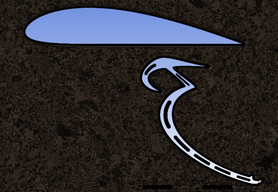
Figure 1. 5.2 design mesh zoomed out

Figure 2. 5.2 design mesh zoomed in
Table 1. Drag of different hanger designs

The following figures below show progressing versions of hanger designs.

Figure 3a. V1.1

Figure 3b. V2.1

Figure 3c. V3.2

Figure 3d. V4.1

Figure 3e. V5.2
Other tasks in progress include designs for the device to lower the hanger and the validation equipment. The device to lower the hanger will use a worm drive flap motor, translating linear motion of the motor into rotation of the hanger that lowers the spray system, shown in Figure 4. For the validation equipment, the initial step involves crafting a frame that securely attaches to the front undercarriage of a vehicle. This frame will extend outward by 6 feet and reach a height of 4 feet, ensuring that validation aircraft is positioned in an area that is free of obstacles that may obstruct or alter airflow, shown in Figure 5. Currently, a design is being developed for the frame to ensure that it can withstand the weight of the validation aircraft, which may include adding wheels to the frame behind the aircraft or attaching to frame points under the hood of the vehicle for stability.

Figure 4. Mechanical device to lower spray system
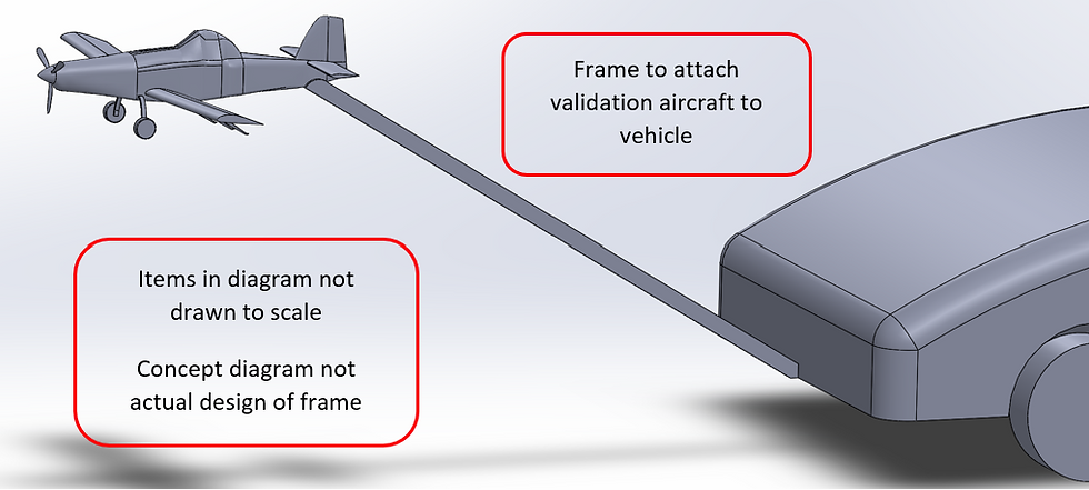
Figure 5. Validation frame concept
Other anticipated obstacles include the FEA after a hanger design is completed and time for the motion transfer analysis and worm gear analysis. For FEA testing, the design may need to be altered to prevent unwanted deflection or structural instability. Professor Love has advised a truss pattern for the internal profile of the hanger to reduce drag while maintaining stability. In the worst-case situation, the structural integrity will be prioritized over drag since the device must be functional. To make up for lost time and prevent further delays, the point of rotation has been locked for all following designs to allow for motion transfer analysis to be completed without having to wait for the final hanger design.
For the next work period ending November 25, it is expected that a final hanger design will be completed, along with the corresponding CFD and FEA analysis. The designs for the device to attach the hanger to the wing and lower the hanger will also be completed with motion transfer analysis and worm gear analysis to confirm the final device’s functionality. A 1:10 scaled CAD assembly of the device attached to the aircraft and spray system will be completed to show how the final design works and produce a bill of materials for all items in the assembly. From the items in the assembly, all parts requiring machining will have proper documents produced per the machinist’s request. This would complete the second milestone of Final Design Completed. Additionally, designs for validation equipment are also expected to be close to finalization to meet the deadline of the last week of class ending December 2.


Comments