Capstone 1 Blog Post 4: Design Review
- Raphael Luu
- Nov 25, 2023
- 3 min read

For the period of November 11-November 25 the team has designed a frame that will attach to the front of a vehicle and extend 6 feet forward and upwards 4 feet, which will then be attached to the back of our validation aircraft. FEA has also been conducted on the validation frame system. Worm gear analysis and motor analysis were conducted to ensure that the gear doesn’t slip when the motor is idle and to ensure that the motor has enough power/torque for our application. CFD on the hanger designs has been completed, with a total of 26 designs tested as shown in Table 1. Of the 26 designs, the one with the lowest drag was modified by moving the point of flow separation vertically and horizontally to analyze its effect on drag. The results of drag vs position of flow separation point were plotted to obtain the best location for the final design, shown in Figure 1 & 2. FEA using SolidWorks Simulation was also performed on the final hanger design upon completion of CFD to ensure that the hanger could withstand the drag and lift forces during flight.

Table 1. CFD Results

Figure 1. Plots of drag at different points of flow separation
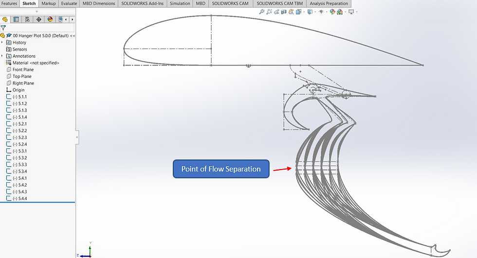
Figure 2. Hanger design selected for plotting (see Fig. 2 for plots)
With the final hanger design completed, the following steps will include finalizing the mechanical device to move the spray system andrendering a full 1:10 scale of the validation aircraft with the spray boom and frame. Following that we will finalize the bill of materials and work towards preparing the necessary documents and files for the machinist to fabricate our design. By the end of this week's work period, we hope to complete our second milestone of finalizing our design and either complete or make significant progress on our last milestone which is the completion of validation of our final design.
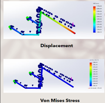
Figure 3. FEA on validation frame
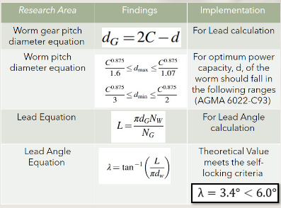
Table 2. Worm gear analysis
The final design of the mechanical device allows for the movement of the spray system by rotating the hangers and is shown below in Figure 4. The hanger geometry has been redesigned to reduce drag at the lowered position. The hanger is also slotted to reduce surface area. The individual mounts on which each hanger rotates are designed with a streamlined profile and a small shaft to allow each hanger to rotate without an exposed connection linking to all other hangers to prevent further drag induction. Once the motor rotates one hanger, the others will be free to follow, lowering the entire spray system. The spray system has been modified with a rigid pipe replaced by flexible tubing to allow for lowering. At full scale, an aircraft flap motor would be used to move the system since it has been proven to be able to operate under flight conditions without problems. One motor will be used on each wing (each wing has 3 hangers) to reduce the load on the motor and keep the spray system balanced on both sides of the plane since the motor will be used as the locking mechanism at the lowered position. For the validation scale, a motor of similar type will be used to operate the device.

Figure 4. Final design
The final hanger design is found to induce only 12.35N of drag at full scale for a single hanger, compared to the 8.12N drag of the original hanger. Although the drag increase is 52%, the difference is only 4N per hanger for 6 hangers which can be considered very little. From FEA, the hanger design is found to have a max deflection of 0.635mm at the free end of the hanger which holds the spray boom. The max stress is found at the point of rotation with a value of 8.743MPa, which is over 30 times less than the yielding stress of stainless steel 316, proving that the hanger is structurally stable (see Figure 5). From motion transfer analysis, it is found that the hanger will rotate 28.15 degrees to lower 1.5ft and move forward 1.2ft. Worm gear analysis has found that a lead angle of less than 6 degrees will prevent slippage while the motor is idle.
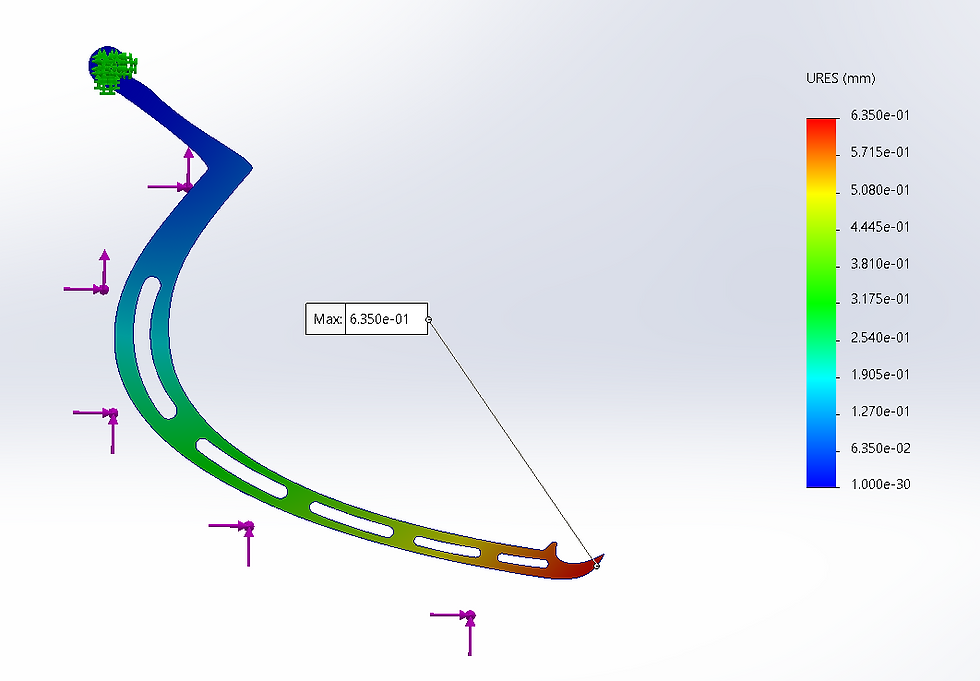

Figure 5. FEA on hanger
Preparations made in advance to prepare for the Spring 2024 semester include sourcing materials and preparing documents for machining parts. Most of the CAD files have been completed and will be converted into proper machining documents before the year ends. Necessary materials as well as the corresponding sellers have been recorded as the project progressed and will be finalized into a bill of materials. Those materials will be purchased ahead of time during the winter to prevent shipping or supply delays and provide a head start. Power tools for construction are currently in the possession of one of the team members. When the Spring 2024 semester begins, the team will have resources to start fabrication and documentation to cooperate with the machinist.


Comments